
Caution: This is a rather lengthy account. It shows several of the techniques I used and may be interesting for beginners or you lot that haven’t started on a moxon yourself:)
I did an earlier study of the moxon, for 433 MHz, and found it very impressive. At the time i did not build a full scale short-wave bands version of it, but the idea of doing so has been there ever since. I felt I was not done with verticals and their possibilities, so my moxoning activities were postponed. After doing the HSQ Beam I was stunned by the experience of good front-back-ration, so the moxon was again to be in focus.
In the meantime I had a rather unhappy affair with a moxon cousin, the hex-beam. I wanted a 3 band version. It turned out to be fairly complicated to string the fishing rod blanks, which I used for spreaders, without reaching the limit where they became fragile. And, so, during some windy days it simply fell over and broke. It was clearly beyond repair, so I dumped the hex-beam ideas. I must emphasise that this is not due to any electrical deficiency of the hex-beam, I still think it would have done an excellent job, but rather due to my poor mechanical skills. Although I am rather a dab hand repairing old cars, antennas are of quite a different nature. So do not let my mishap stop you from building a hex-beam. But keep clear of the fishing rod blanks.
A positive outcome was that from the hex-beam debris I managed to salvage parts enough to put together four spreaders, each 410 cm long. And four spreaders is exactly what the moxon needs, so…
Even though the moxon is small compared to a normal two element beam, about 70 percent, it still is big when made for 10 MHz and below. I really would like to have one for 10.1 MHz but its dimensions are simply too large for me. I do not have a tower to put it on, it will have to be fitted to the chimney, and there it will compete with the TV-antenna on a chimney next to it. I settled for 14 MHz, as this is a band that promises some long haul DX, even during times of low sunspot activity. It would have been easier to make an even smaller one of course, but 18 MHz and above are not that much open nowadays, unfortunately.
Sticking it into the chimney and the fact that I have no rotator, calls for some thinking before acting. Mechanically it can be difficult to hoist it up into place and then it will have to point in “the most favourable direction” – whatever that is? So it had to be installed in pieces, as a kit while on the roof. And would it not be a good thing to make the moxon reversible? So that its direction can be changed by easy means? Of course it would! My ponderings that led to this “insight” is described here
Making a driven element-parasitic reflector combo reversible means changing the feeder from one element to the other and loading the unfed element, thus effectively making it into a reflector. The “standard” moxon is not symmetrical, the two elements are of different sizes, the reflector being the longer one. Simulations show that a moxon with exactly equally sizedelements can be made reversible by loading the reflector with some 60-70 ohms and feeding the other element. This is what AA2NN has done and which is described in detail in ARRL book “Fun and simple antennas for Hams” (much recommended by the way).
To keep the weight down I made a centre hub as per K4QKY’s description. This is the easiest and most lightweight way of doing it, methinks. Onto each of the four pole holders I threaded the fishing rod blanks and secured them with clamps. The poles were 4.10 meters long and were pushed almost together with the one opposite before securing it. I then put the hub onto a metal 40 mm mast and tied lines between the ends of each opposing fishing rod pair, and taut the lines so that the rods’ ends lifted about 30 cm. To relieve strain on the rod ends I put a small clamp at the outer end of each rod. This is absolutely necessary as otherwise they will rupture! The lines were fastened at these ends by a knot around a spike which was then put inside the tube.

Centre hub with fishing rod blanks attached. Truly light weight!
Separately I prepared the antenna wire, I used standard 0.75 mm2 stranded cable with the insulation stripped off (this way I don’t have to care to re-scale the lengths from my simulations due to the wave velocity). As this will be a symmetrical antenna I needed four lengths of wire each 508 cm long.
Out of plastic I sawed the necessary insulators, two to separate the sides of the moxon and two centrepieces. The centrepieces are as short as possible, just leaving a distance of some 2cm between the wires. To keep the moxon rectangles’ most critical dimension, the space between the elements ends, I drilled holes in the plastic exactly 19 cm apart.
With the insulators thus in place, the entire wire/insulator assembly was fitted onto the square. I made certain not to let the rectangle’s corners extend all the way out to the clamps and spikes, I used a short insulating line (about 5 cm) to separate the wire corner from the metal of the clamps. This is perhaps an unnecessary precaution, but it is easy to do it. What might not be so unnecessary is to put some plastic tape around the wire corner to relieve the strain on it, or it will bend and eventually break.
For quick and easy testing of the antenna, I made it temporarily unidirectional by loading the reflector element. For loading I used a “hairpin match”: two parallel lengths of copper wire spaced about 3 cm and about 70 cm long was fitted to the reflector element’s centre. With two alligator clips soldered back to back I could short the parallel wires at different positions and so change the amount of loading used. Trimming of this is simple given a constant signal from the back direction, just move the two clips up and down the hairpin until the signal is at its weakest.

Tuning the reflector can be done with a hairpin match. It is much easier than trimming the reflector’s wires by cutting or lengthening them.
Theoretically, the loading should be about 65 ohms, which at my design frequency of 14.050 MHz translates to about 0.8 uH. This inductance can be obtained by a piece of shorted transmission wire (the hairpin). The exact length of the transmission wire can be calculated as it depends on the characteristic impedance of the wire. But that is not really necessary since a length of 70 cm includes all possible reasonable inductances. And some final trimming will be necessary anyway. Look at the footnotes on this page for exact calculations (needed for other bands).
As a “proof of concept” I installed the contraption at a height of 3 meters in my garden. This way I could easily reach the alligator clips and adjust the hairpin for best rejection of rearward signals. There was a decent minimum of the signal but not at the point on the hairpin where the theory predicts it! Perhaps the main wire lengths are a bit off (even though I measured twice before cutting:), perhaps the ground has some effect, or the aluminium ladder I used? I don’t know, and don’t really care as long as there is a minimum. This shows the need for final adjustments. Anyway, it proves that the unidirectionality is there and the loading is in the right neighbourhood – or thereabout.

My first Moxon in the air! From here I could easily adjust the hairpin for best F/B.
I put the coax into my KX-1 and listened. Nothing. But that was because it was directed due west, turning it south revealed several European stations, amongst them a Spanish station which promptly recalled my call. Running about 1-2 watts, with an antenna 3 meters up, I was impressed. During my next over, I sent a row of “dits” and rotated the antenna. The Spanish station was surprised of the sudden QSB:) Later at night I also had a QSO with Guyana, my first 8J!
I later equipped this moxon with two feeders. One of which is shorted to act as a loading and adjust its resonance frequency to some lower value. The technique is described at the end of this page. Trimming was unexpectedly easy: The wire cutter I used made a short between the inner conductor and braid of the reflector’s coax before cutting it off, so I had an easy means of cutting slowly and reading the signal strength before cutting the coax completely. This way I started with a coax about 1 metre longer than calculated and trimmed in increments of about 2 cm until the signal began to drop and simply stopped cutting when the signal was at its lowest. Then I switched feeders and repeated the procedure with the other reflector’s coax. I finally put a small switch-box with two relays in it and put that just below the antenna midpoint, under the centre hub. This is to be recommended as the quick change of direction of the beam is a very nice feature. And having only one feeder into the shack is easier to manage (and the power loss in one coax is less than the loss in two of them).
It might be of interest to document the antenna’s performance at this low height: Calculated and cut for 14.05 MHz it seems to have its lowest SWR just below 14 MHz, with acceptable (<1.5) SWR in the entire band. I lengthened its tail with about 4 centimetres and then it fell spot on 14.060 MHz. Testing with a TS-930 it has a F/B-ratio of 3 to 5 S-units when properly trimmed at this low height above ground level. Its resonance is expected to rise as the contraption is installed at a more suitable height. It is however fairly wide in both SWR and F/B so this should not cause any problems.
Simulated results, which I find not much to argue against, are shown below. The first one is the radiation pattern at a mere 3 metres above ground level, the second at a more proper height of 10 metres. Already at lower heights it is clear that the Moxon has some clear benefits. An omnidirectional horizontally polarised antenna would at this height have a main lobe pointing straight up, something a moxon avoids.

Already at a few metres above ground (here 3 meters) the unidirectionality is beginning to show. While not “DX” at 53 degrees elevation angle it is definitely more so than the equivalent dipole at the same height. This is the height I used for trimming the reflector for best F/B. I imagine a greater height would have been better but the performance on top of my chimney later was OK anyway.
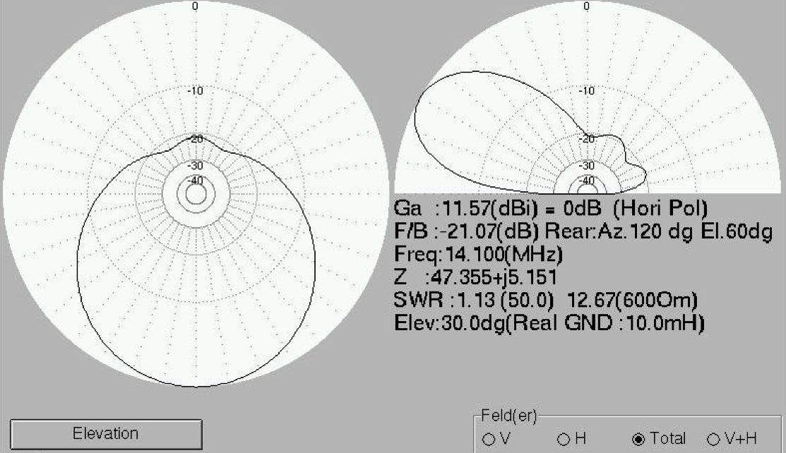
The moxon 10 metres up. This is a fairly typical diagram of expected performance. At reasonable heights it is not likely one would get better F/B than about 20 dB:s.
Proper height depends on the band used, but simulations indicate a height of around half a wavelength to be the lowest one for best performance. Higher than that will produce another lobe pointing upwards, a lobe which will turn closer to ground as it is raised even higher, until another lobe appears and so on. Just short of any multiple of one half wavelength seems to be the best. Look at the diagrams for the 433 MHz (70 cm wavelength) version, there are many lobes there indicating the height.

Diagram showing the effect of the antenna’s height over ground. One lobe is added per half wavelength height, so during this simulation at 70 cm wavelength a height of 3 meters was used.
Footnotes
How to calculate hairpin dimensions
Given the inductive impedance of 65 ohms, we need to find a hairpin for that inductance. We also need the transmission lines’ characteristic impedance. Follow the steps below:
- Find characteristic impedance of the transmission line, Z0. With wire diameter d and distance between the parallel wires D, then Z0=276*log(D/d). Use same units for d and D, log is the logarithm with base 10.
- Calculate length in degrees of required transmission line, 65=Z0*tan(l). l=atan(65/Z0).
- Find the wavelength i meters by 300/frequency i MHz.
- l now is transformed from angle to length, by observing that at full wavelength is 360 degrees. Required length of transmission line is then (l/360)*wavelength.
Alternatively one can calculate the inductance by the relationship 65=6.28*f*L, where f in Hz gives L in Henrys and wind a small coil. This has exactly the same effect as the hairpin but involves more work. The inductance can be trimmed somewhat by squeezing the windings together or pulling them apart.
For a frequency of 14.05 MHz, and transmission line with d=0.7 mm, D=30mm:
- Z0=276*log(30/0.7)=276*1.63=450 ohms.
- l=atan(65/450)=8.2 degrees
- wavelength=300/14.05=21.35 meters
- (8.2/360)*21.35=0.49 meters
So the clips should be attached 49 centimetres from the end. Try these calculations with different size of the transmission-line and it always boils down to about the same dimensions. In this case obviously there is not much point in being overly precise. Adjustments take care of the imprecisions.
With 50 ohm coax simply use this value of characteristic impedance in the formulae above. Remember that a length that is any multiple of a half electrical wavelength will reproduce the same loading. If you decide to use two feeders and want them all the way into the shack just make them the required number of half wavelengths longer before the final trimming.
